Recently one of my partners called me as they had some issues with their customer and they didn’t have any network specialist in-house. Its network performed poorly, regular disconnections from wifi, Internet slowness, VoIP calls dropped.
The building of the customer is composed of 3 floors in the center of Brussels. The building has been well renovated.
The customer’s employees work mainly with Cloud based applications. As we are talking about a real estate company, it is important to consider that the customer works with big files (pdf, MS word, maps and so forth. So, in that case, it’s critical that the network performs well.
Characteristics of the infrastructure:
Number of users: +/- 20 (1 site)
Type of devices: VoIP phones, Laptops, Desktops, MFP printers,
Type of Network: Wired + Wireless
Internet Line: Fiber 500 Mbit/s symmetric
Network Switches: 4 different models / specs
AP: Cisco Meraki Go AP (802.11ac capable)
Firewall: Fortigate 60F
Constraints:
very limited budget (implies re-use of existing equipment)
Network cabling coming from the different rooms to the patch pannel are CAT 5E STP
Identified issues:
Network switch topology (Daisy Chain)
Mixed switches architecture (1Gbit/s mixed with 100 Mbit/s – old Cisco SG series)
Flat network (no VLAN) – All types of traffic running on the same /24 subnet.
Firewall issue (Firewall not responding correctly on LAN interface & limited bandwidth)
No structure in cabling
Network cabinet not maintained correctly
No restrictions on outgoing traffic (LAN -> WAN)
Cabling from patch pannel to network switches were UTP (very bad due to electrical interferences)
The solution:
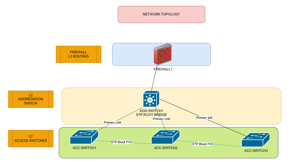
Network topology review:
Instead of using a daisy chain topology wich increase the latencies all along the switches, I’ve decided to move to a 3-tier topology ( FW – AGG Switch – ACC Switch). Due to the limited budget making a redundant setup at Firewall and AGG switch was not possible. Planned for later. The switch with a max bandwidth of 100Mbit/s has been removed. New Cisco Catalyst 1200 have been bought to give more freshness and robustness to the infrastructure. VLANS have been defined to isolate main types of traffic and optimize network segments. Introduction of a guest wifi attached to a specific vlan.
The new topology can be depicted as follow:
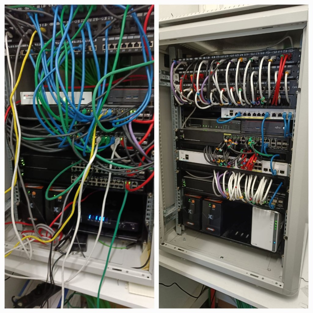
Network Cabinet review:
Introducing cable management between switches to permit easier maintenance and air flows. To ensure a perfect stability of the data running on the cables, all of them have been replaced by STP (Shielded Twisted Pairs CAT 6 cables). Labeling rings have been placed on the cables to easily maintain and troubleshoot. Proper color convention has been established based on the type of devices.
Firewall Replacement:
As the firewall had a lot of issues, it has been replaced by a new one. Outgoing traffic (South -> North) has been limited with L7 features included.
Before/After Snapshot:
Notes:
At the moment of the picture the faulty firewall was replaced by a old Fortigate 80C. As from March 2025, the new Fortigate F60 is working flawlessly.
At the moment of the picture the STP topology was not configured, in between it has been implemented
Client / Partner reaction:
Both are happy:
the Cloud applications has never been so responsive.
Very quick printing and scanning over network
No more issues with VoIP calls
Internet can be used at full speed: 480Mbit/s UP & DOWN
Wifi association process is very fast
My 50 cent on this project:
Funny fact. I could observe on this mission that I needed a CAT6A (10Gbit/s) cable to connect the Firewall to the Internet modem and AGG switch to take advantage of a 1Gbit/s bandwith. Using CAT6 or CAT5E cables on the firewall reduced the usable bandwidth to 100 Mbit/s. I will investigate later…
Thanks for taking time to read this showcase. I hope that others will come. Feel free to reach out for any remarks or questions.
You are interesed to work with me, don’t hesitate to book an appointment via the Calendly widget
I work with VMware Workstation for a while and it’s an amazing tool. It permitted me to create some labs, demos for customers, prepare myself for IT exams, and even shutdown fire on production environments.
That being said, the most challenging part with VMware workstation is to simulate enterprise network on your host machine where VMware workstation is deployed. To simulate enterprise network you need to be able to virtualize routers, Firewalls, deploy VLANs and many other stuff…
And here it is… 🙂 A key foundation of modern networks is segregation of the physical network by the implementation of VLANs.
If you’re not familiar with VLANs, you can see that as a logical split of your network in different pieces.
Practical example: Your physical network is an hotel and in this hotel, you have multiple floors. Each floor can be seen as a VLAN (it is a logical segmentation). Each room in each floor can be considered as an IT device (server, workstation, printer…). To navigate within the different floors you need to use stairs or elevators. Those ones are your routers or firewalls of a network. They permit the communication between your subnets or VLANs.
A clear technical explanation is given here for those who are not familiar with VLANs:
Probably you already know it, but it’s a good time to recap as it will be necessary for the final purpose of this blog post! Playing with VLANs on VMware Workstation!! It rocks!! 😉
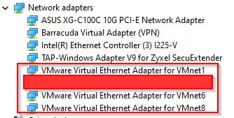
When deploying VMware Workstation on a Windows machine, it creates 3 additional NICS on your machine. You can see them in the Windows Device Manager as you can see here:
Yes!!! I hid one as this one is related to a specific setup – You will understand later ;-). But let’s be pragmatic and let’s consider that I have a regular setup.
Each card has a specific role:
VMnet 0 works in Bridge Mode.
VMnet 1 works in Host-Only Mode.
VMnet 8 works in NAT mode.
What does it mean?
Bridge Mode
When you create a VM on VMware Workstation and you attach its vNIC to VMnet0 (default) physical Adapter. The VM is directly connected to your physical network, because on top of being a layer 2 switch emulated (VMnet0), it has a function of L2 Bridge.
It’s the easiest mode when your VM doesn’t require a complex network setup and security is not the first concern. Typically, it’s the best use case to quickly offer connectivity to your VMs in a homelab environment.
Host-Only Mode
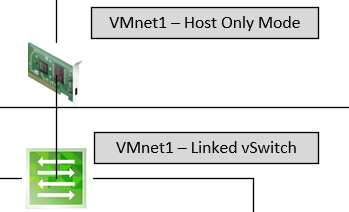
When you create a VM on VMware Workstation and you attach its vNIC to VMnet1 (default) physical Adapter. The VM resides in its isolated network which is defined at the VMnet level. In the example above the VM resides on the network 172.16.10.0/24 with no option to go outside this network. Even when you try to configure a static IP on it with its related DNS and default gateway. From your host machine, you cannot reach the VMs via the network neither.
If you want to build a lab that doesn’t requires any connectivity outside the network that VMware Workstation built for it, it’s the way to go.
It exists a workaround for this 🙂 🙂 : You can deploy a virtual Firewall or router which should be connected to this isolated network for the LAN part and connected in Bridge Mode for the WAN part. This router/firewall should be configured as the default gateway for all the VMs being part of this isolated network and boom!! Your “isolated network” has a connectivity outside its bubble. OR, you use the built-in solution from VMware –> NAT Mode
NAT Mode
This one is a little bit more interesting 😉
If I want to make it short: IT’S HOST-ONLY MODE WITH A BUILT-IN NAT DEVICE (L3)
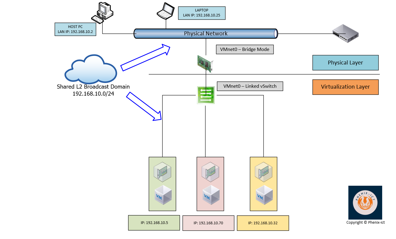
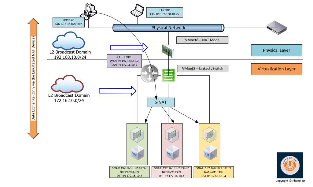
As you can see on the schema, your host PC resides on the network 192.168.10.0/24. When VMware Workstation is deployed it will create a physical network adapter on this host (VMnet 8 – by default) with NAT capabilities. Your VMnet8 act as a router/firewall with NAT functionalities. This device will share the host IP on the physical network (192.168.10.2 on the schema). On the NAT device (VMnet8), this interface is considered as the WAN interface. Regarding the LAN interface of this device (VMnet8), it will reside on the isolated network (172.16.10.0/24). In the example depicted here above, it has been attributed the IP 172.16.10.1.
All the VMs in this isolated network will use VMnet 8 internal IP (172.16.10.1) as their default gateway to reach the outside world.
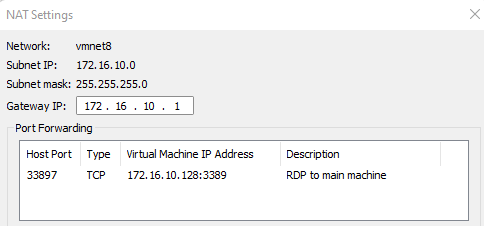
From the perspective of the devices (pc, laptop, printer, ISP router…) connected to the physical network, the VMs residing on the isolated network are only reachable via the IP of your host (192.168.10.2) on specific ports that you defined in the NAT settings as shown here under.
If you are familiar with the deployment of containers via Docker on your machine, the concept is very similar. You access your containers via NAT(ed) ports.
On the perspective of the VMs residing in the “isolated” network, the outside world is reachable via the IP of the NAT device (172.16.10.1) which is in fact VMnet8.
NOW that the foundation has been covered, let’s talk about the VLAN support, which is what you’re looking for 🙂 🙂 :-).
VMware workstation is a VLAN-aware software.
Theory:
In theory VLAN ID range start from VLAN 0 to VLAN 4095 but some of them are reserved.
VLAN ID 0: Is like no-vlan. No VLAN information is sent over Ethernet Frames (No VLAN Tagging at end-device level | read PC) VLAN ID 4095: is like all-vlans. The switch will send all VLAN Tags over the Ethernet Frames. Typically, in VLAN world it is considered as a TRUNK
If you want more information about VLANS, I suggest you google a little bit, but here are some references:
The following statement is crucial: Your VMnet (x) NIC created during the installation of VMware workstation must been seen as a L2 switch. You add limited L3 functionalities in NAT mode.
As a reminder, you could see that in my schemas, I draw this important concept.
So, from there, as any L2 manageable switch, you can configure VLANs on it, but how?? 🙂
To do so, the “only” thing to achieve is to render the VMnet NIC you want, VLAN-aware by setting up the correct VLAN ID.
The VLAN that will do the trick is VLAN ID 4095
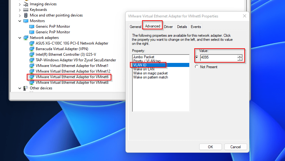
To do so, go on the device manager of your Windows machine and define VLAN ID 4095 on the VMnet NIC that you will use for deploying VLANs for your virtualized environment.
From there, all the VMs that you will attach to this VMnet device, must be VLAN-aware (refers to VGT described earlier). As VLAN tags will be passed to them. Typically, all types of devices where VLAN trunking driver is embedded in the vNIC driver.
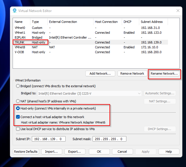
Advice: In the Virtual Network Editor of VMware Workstation, I strongly advice you to rename the VMnet adapter as your setup can become complex
Here is an example of the setup you should have in your Virtual Network Editor
Note: The Subnet defined on this adapter becomes unavailable when you enable VLAN ID 4095. In my case, I first configured my virtual firewall via this interface before enabling VLANs on VMnet device.
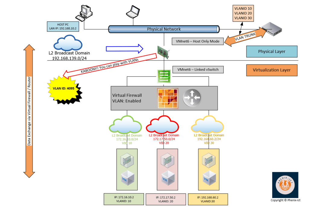
Here is an example of the target topology.
Important note: You must define on your physical switch the same VLAN IDs as you define in your virtual environment on the port where you connect your real physical NIC (VLAN Trunk on the schema)
Use-case
To pass my VMware NSX certification, I needed to play with a lab at home. To limit the physical footprint of a such lab, I decided to virtualize a full ESXi cluster with vCenter and NSX enabled on my physical host. Forget about implementing a such virtual infrastructure without VLANs especially if you want to play with NSX 🙂 🙂
Conclusion
I hope you enjoyed the information you found in this article. Please, don’t hesitate to comment as it will help me, to give you more content as that one, and maybe with a better quality.